2005
There were 39 students enrolled in ECE 457/458 Design Project I/II, the capstone design experience where students expand their abilities and develop important real world engineering problem solving skills. The students were divided into ten groups. The details are given below.
| Project Title | |
|---|---|
| Group 1 | GPS/INS Subsystem for DARPA Grand Challenge Vehicle |
| Group 2 | Water Quality Monitoring System |
| Group 3 | Radar Subsystem for DARPA Grand Challenge Vehicle |
| Group 4 | Subsystem Monitor |
| Group 5 | Laboratory Security System |
| Group 6 | LIDAR (Light Detection and Ranging) Medium-Range Obstacle Detection System for the DARPA Grand Challenge. |
| Group 7 | Test Program Set (TPS) for the Virginia Class Submarine DC Relay Circuit Card Assembly |
| Group 8 | Smart Caddy: A Golf Bag Carrier |
| Group 9 | Terrain Mapping By Use of Radar |
| Group 10 | Power Controller |
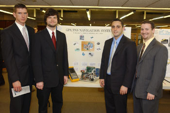 |
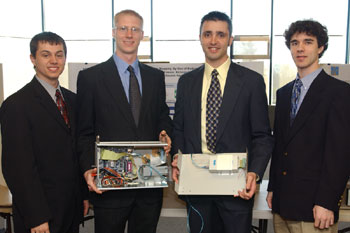
Group 1
Student Members:
Nathaniel P. Barcelos
Christopher M. Baron
Adrian J. Gonsalves
Jacob S. Olson
Faculty Advisor:
Professor Robert Helgeland
Project Title:
GPS/INS Subsystem for DARPA Grand Challenge Vehicle
Project Description (provided by group):
The purpose of any navigational system is to provide the user with a location of whatever it is that the user may happen to need. In most cases, what the user needs is location of where they are so that they can avoid getting lost and help find their desired destination.
The main area of focus for our system is to provide the Dartmouth Autonomous Vehicle (DAVe) with the most accurate assessment of where we believe the vehicle is at all times, along with the confidence and current health status of our system with respect to the vehicle. We summarize all this information into the vehicle's state. State consists of latitude, longitude, altitude, vehicle orientation, velocity, and overall system health.
We incorporate different types of technology together in our system. We integrate a Global Positioning Sensor (GPS), an Inertial Navigation System (INS) which is comprised of Accelerometers and Gyroscopic sensors, along with a wheel encoder and binary counter to calculate the state.
Many problems exist with using only one of these types of technology. GPS devices typically provide accurate data for long distances and periods of time while providing inaccurate data for relatively short distances and periods of time. INS devices provide information that gets exponentially worse with respect to time and typically are only useful within the first few minutes after initialization. The wheel encoder outputs the wheel velocity which gives us accurate wheel speed data and provides us with another means of determining position by combining how far the vehicle moved with the direction in which it moved.
Combining all three of these devices enables us to dramatically improve the system accuracy as well as verify the confidence of each device output. If one device is returning faulty data, or no data, the other two devices will notice what is happening and pay little attention to it. We feel that this design gives us the most accurate results possible with the budget and timeline with which we were provided.
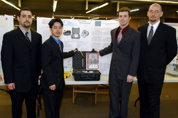 |
Group 2
Student Members:
Brian Daniel Crispim
Matthew J. Cody
Michael M. Enos
John Tang
Faculty Advisor:
Dr. Lester Cory
Project Title:
Water Quality Monitoring System
Project Description (provided by group):
The Water Quality Monitoring System is a data recording device which handles multiple analog signals. The system features four analog channels for recording data up to four different types of water quality measuring sensors. There are three sampling rates in which the system can run; minute, hour and day. Each data recording is stored on a removable flash memory card carrying with it a date/time stamp.
The PC Software Package, accompanying the system, allows the data recorded to be displayed in an easy to read format. For extended use of the recorded data, the PC Software Package allows data to be exported to Microsoft Excel.
The system is also provided with a lockable, weather-resistant enclosure. The enclosure can be hidden and will provide protection to the system from the environment. The system comes with a battery with the ability to sustain the system for an extended period of time varying with the chosen sampling rate.
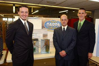 |
Group 3
Student Members:
David A. Hague
John Lima
Eric M. Scanlon
Faculty Advisor:
Dr. Dayalan Kasilingam
Project Title:
RADAR Obstacle Detection System for DARPA Grand Challenge Vehicle
Project Description (provided by group):
The Departments of Electrical and Computer Engineering of the University of Massachusetts Dartmouth has entered a competition sponsored by, The Defense Advanced Research Projects Agency (DARPA) called the Grand Challenge 2005. The Defense Advanced Research Projects Agency (DARPA) seeks to promote innovative technical approaches that will enable the autonomous operation of unmanned ground combat vehicles.
The scope of team 3 project is to develop a RADAR Obstacle Detection System to be mounted on an off road (DARPA) vehicle. This system will feed a navigation system which will attempt to make intelligent decisions on the vehicle's next move based on incoming sensor data.
The final design for the Long Range Obstacle Detection System consists of a Continuous-wave RADAR that is responsible for transmitting and receiving a signal, which will allow us to detect objects in the path of the DARPA vehicle. In order to detect objects, we must send a pulse and be capable of receiving that same time delayed pulse. By measuring the delay between the transmitted and received pulse, we can calculate the range of the obstacle. A Continuous-Wave RADAR can implement this pulsing technique by using Frequency Shift Keying. What this means is when the low part of the pulse wave is transmitted, a lower frequency sinusoid wave will be transmitted. When the high part of the pulse wave is transmitted, a higher frequency wave will be transmitted. This will allow us to pulse with continuous-wave RADAR. In order to pulse the RADAR, a Pulse Generator is used to develop a pulse train which in turn drives the modulator on the radar transceiver.
In order to measure the time delay, the received signal must be passed through our two-stage amplifier in order to make the signal compliant with the hardware we used. Then the two pulse trains go through comparators to digitize the signals. We then used a Binary counter driven by an oscillator to count the delay between pulses. When a pulse is transmitted, the counter starts counting. When a signal is received, the counter stops counting. This binary number will be sent to the microprocessor. The microprocessor will use a look up table to match that binary number with a specific range. This range will then be sent via a TCP/IP port to the DARPA Vehicle's CPU for necessary decision making.
 |
Group 4
Student Members:
Yves Hajjar
Shawn Buttrick
Chris Chapman
Jean Saint-Cyr
Faculty Advisor:
Dr. Paul Fortier
Project Title:
System Monitor
Project Description (provided by group):
Apollo 50 is a Rabbit microcontroller-based monitor system. It communicates with Sun servers via wireless transceivers. Commands are sent by the Rabbit microcontroller and responses from Sun servers are analyzed. Sun status information is extracted from the responses and stored. Apollo 50 in turn updates a web page with the collected status information. Apollo 50 is also capable of sending email notifications when a problem occurs with a Sun server.
|
|
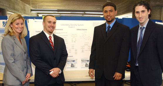
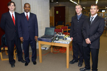
Group 5
Student Members:
Stephanie Leahy
Matthew Hoeg
Manny Montrond
John Gifford
Faculty Advisor:
Dr. Gilbert Fain
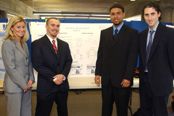
Project Title:
Laboratory Security System
Project Description (provided by group):
The main goal of this project is to design a working security system. This system is set up to take pictures or videos in ECE lab rooms 217, 221, and 222. There are two different modes of operation that have been set up on each of the computers, 1. Day Mode, 2. Night/Weekend Mode. During the Day Mode the camera is set up to take and record pictures every 3 seconds. This will allow the user to monitor the lab rooms during the hours of operation. During the Night/Weekend Mode the camera is set up to record videos whenever there is motion detected in the lab. The video will continue for 30 seconds and then wait for motion to be detected again. If motion is detected after these 30 seconds are over then the video will begin again and be recorded as a different video. This will give the viewer plenty of time to replay the short videos as many times as necessary to figure out the demographics of the unwanted motion.
The user is able to access these pictures and videos through a database that is accessible via the Internet. The user friendly website has a display screen that the user is able to click on each lab room, which will show them every picture that has been saved over the past 48 hours. If there have been any videos that have been recorded in the past 48 hours then they will also be accessible. After the videos and pictures have been accessible for 48 hours they are deleted from the database. The cameras are connected to the computers using RG-59 cable. The computers are each connected to the network using Category 5 Coaxial Cable that has been weaved through Group 2 (The Science and Engineering Building).
The motion sensing that is directly from the ConquerCam software is activated when the software itself recognizes a change in pixels in each frame. In order to make this happen, we have connected a motion sensor to a lamp to add more light to the room. This low lighting activates the ConquerCam motion sensing, which begins the video taking, but will not give the intruder any unnecessary light.
This security system will hopefully help the ECE department to prevent and destroyed or stolen items in the lab rooms. If there was more time we would have been able to secure more than four lab rooms, but because of the normal problems that we encountered and the necessary solutions there was no time to go above and beyond the requirements.
|
|

Group 6
Student Members:
Ernest Northardt
Ryan Kelly
Brian Fredette
Ifeany Gusiora
Faculty Advisor:
Professor David Lincoln
Project Title:
LIDAR (Light Detection and Ranging) Medium-Range Obstacle Detection System for the DARPA Grand Challenge.
Project Description (provided by group):
The DARPA Grand Challenge vehicle here at UMASS Dartmouth needs various on-board obstacle detection systems. Once such sub-system is a LIDAR Medium-Range (30 - 100m) sub-system. The System uses lasers to determine the distance to targets within the field of view of the DARPA vehicle and outputs the measured data to the DARPA vehicle artificial intelligence host computer.
|
|
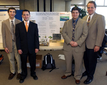
Group 7
Student Members:
Stephen J. Valois
Thomas Schwinn
Peter Wheeler
Daniel Rodrigues
Faculty Advisor:
Professor Philip Viall
Project Title:
Test Program Set (TPS) for the Virginia Class Submarine DC Relay Circuit Card Assembly
Project Description (provided by group):
Raytheon Integrated Defense Systems has received follow-on contracts from the US Navy to provide program management, systems engineering, configuration management, and materials procurement for the manufacture, test and integration of the combat control group subsystem of the VA Class attack submarine. As part of the on-going effort to reduce manufacturing costs in order to meet contractual requirements, the VA Class PMO is constantly looking for ways to improve manufacturing test efficiency. The DC Relay module which is a subsystem of the combat control system is a perfect candidate for a test automation upgrade as it is currently bench tested at a minimum of 4 hrs with an engineering Design Verification Test (DVT) box. The team successfully converted the manual manufacturing test to an automated test station controlled by a PC. The test time has been reduced to 95 seconds from 4 hours.
|
|
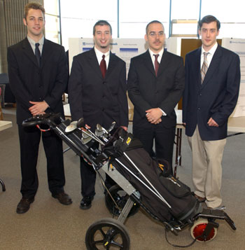
Group 8
Student Members:
Greg Caron
Jason Marques
Dan Lamontagne
Mike Kelly
Faculty Advisor:
Hong Liu
Project Title:
Smart Caddy: A Golf Bag Carrier
Project Description (provided by group):
To build, test, and document a prototype for a semi-autonomous, battery powered golf bag carrier. It should be able to handle the rigors of a typical golf course, and power should be able to last the duration of a typical round. It is to have a projected retail price of $1500 and the integration of motors, motor controllers, batteries, battery management (including recharging) is required. Current products do exist, and our goal is to alleviate some of the major issues, including weight, collapsibility, and ease of use.
|
|
Group 9
Student Members:
Jeff Magalhaes
Nicholas Klassen
Nicholas Swieder
Mark Dunn
Faculty Advisor:
Dayalan Kasilingam
Project Title:
Terrain Mapping By Use of Radar
Project Description (provided by group):
The purpose of our project was to create a sensor for the UMASSD Darpa vehicle, DAVe. Our sensor will determine what type of terrain DAVe is on and convey that to the main AI of the vehicle so that an intelligent decision can be made on what actions the vehicle should make. Our sensor operates on the principles of Frequency Modulated Continuous Radar and on the backscatter effects of Radar. Based on power of the received signal and the time delay of receiving that signal, we are able to determine what type of surface is most likely in front of the sensor. Harder surfaces return higher power signals, while surfaces like water and brush return lower power signals. This helps the vehicle determine how fast it should be going and whether or not to stop and investigate the upcoming course.
|
|
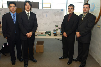
Group 10
Student Members:
Takahiro Kimura
James W. Davidson
Brian Mello
Harry D. Nunez
Faculty Advisor:
Dr. Gilbert Fain
Project Title:
Power Controller
Project Description (provided by group):
Team ten constructed a functioning prototype of a Power Monitor for a Long Island based power company, All-City Switchboard Corp. The power monitor has a range of operating voltages, from 120/208VAC to 347/600VAC three phase. The unit is also self-powered through line voltages.The basic overview is that it monitors the current, voltage and phase rotation to a given load. It is also able to monitor a temperature through a set of inputs. These different detections are selectable through a menu system that we have implemented. If the customer wants only a certain detection to occur, they have a way to select the appropriate detection. Thresholds for the different detections are entered into the menu.If the controller detects one of these faults, (i.e. the thresholds are surpassed) the controller activates a relay that has been preset by the user. A special case is called the shunt trip, which cuts power to a load. These relays can withstand a 10A load at 120V. The main key point about the relays is that they can be interchangeable from one detection circuit to the other via the menu selection.